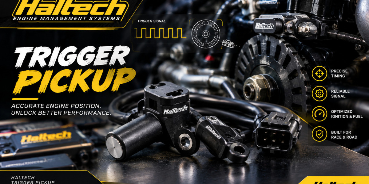

Choosing a trigger sensor for a standalone ECU seems simple until you try to match all the variables, the engine wheel, the sensor technology, the ECU model, the software pattern list and the wiring. A mismatch at any point can mean a non- running engine and it is often unclear where the fault lies. This guide focuses on Haltech trigger pickup compatibility with ECU hardware, with particular attention to the Haltech Elite ECU and Haltech Nexus ECU families.You will learn how to check each compatibility layer, how a typical Haltech trigger pickup wiring diagram is structured, how to handle cam inputs and how to troubleshoot when the engine will not sync. The goal is a methodical approach you can apply to any engine, from a factory wheel swap to a custom motorsport build.
Understanding the Haltech Platform
The Haltech engine management system is a family of programmable ECUs used in street, drift, circuit, rally and drag applications. The Elite range and the Nexus range differ in their hardware design, available inputs and outputs and software environment, but both are built to support a large library of trigger patterns and to give the builder flexible sensor options.
Because models vary in the number and type of inputs, never assume that a feature on one ECU exists on another. The sensible approach is to look up the exact model, read its wiring and pin documentation and confirm the trigger and home input specifications before ordering a sensor.
The Four Layers of Compatibility
Compatibility is not one question but four. Work through them in order.
Layer 1 Mechanical Compatibility
Will the sensor physically fit and read the wheel? This covers thread size, body length, mounting style and the sensor's position relative to the teeth. It also covers target compatibility; the sensor must be designed to detect the material and shape of the target. A VR sensor needs a ferrous tooth and a Hall sensor must be matched to its target design.
Layer 2 Electrical Compatibility
Does the sensor's output suit the ECU input? A two wire VR sensor feeds an input configured for VR. A three wire Hall sensor feeds an input configured for Hall and needs a supply that matches its rating. Check the supply voltage range, the output type (push pull or open collector) and whether a pullup is needed.
Layer 3 Pattern Compatibility
Does the ECU's software include the trigger pattern that matches your wheel? Haltech software supports a broad library of factory patterns and common aftermarket wheels such as missing tooth layouts. Check the pattern list for your engine and read any notes about whether the pattern needs a separate cam or home signal.
Layer 4 Configuration Compatibility
Are the software settings correct? This includes input assignment, sensor type, edge polarity, cylinder count, firing order and the trigger offset. Even with compatible hardware, a wrong setting leads to a non-starting engine or incorrect timing. If all four layers align, the system will work. If it does not, the layered approach shows where to look.
Trigger and Home Inputs Explained
In Haltech terminology, the main crank signal enters through the trigger input and the cam or phase signal enters through the home input. Some patterns need only the trigger, while others require both.
A crank trigger system with a missing tooth wheel and a cam signal gives full sequential capability. The camshaft position sensor on the home input tells the ECU which revolution is in progress. When a cam signal is not available, many engines can still run on the crank signal alone with batch injection and wasted spark ignition.
When evaluating a donor engine for a swap, count how many crank and cam signals it provides, determine whether they are VR or Hall and identify which ECU inputs will receive them. Factory engines vary widely, with some using VR crank sensors and Hall cam sensors and others the reverse.
Choosing Between a Factory Sensor and an Aftermarket Kit
When the engine has a factory trigger system, the easiest path is often to reuse it, provided the ECU supports the pattern. This preserves the original wheel and bracket geometry, which are already matched to the engine.
When the factory arrangement is unsuitable, or the engine has no trigger wheel, a Haltech trigger sensor kit or another aftermarket crank trigger system can supply a wheel, bracket and sensor designed to work together. Kit advantages include known geometry and predictable signal quality. Disadvantages include the need to fit the wheel to the crank pulley or balancer correctly and the cost. For custom builds, always check that the wheel's pattern is supported by the ECU. A beautifully machined wheel is useless if the ECU cannot decode its tooth layout.
Reading a Trigger Pickup Wiring Diagram
A Haltech trigger pickup wiring diagram typically shows the sensor, the cable, the shield and the ECU pins. Although the exact pin numbers depend on the ECU model, the logic is consistent.
For a VR sensor
Sensor wire one connects to the trigger input.
Sensor wire two connects to the matching return.
The shield goes to a clean ground at the ECU end only.
For a Hall sensor
The supply wire connects to a suitable sensor supply.
The ground wire connects to the dedicated sensor ground.
The signal wire connects to the configured digital input.
The shield goes to ground at the ECU end.
Always use the diagram specific to your ECU and sensor and mark each wire clearly. Mixing up supply and signal on a Hall sensor can damage it and reversing VR polarity can cause the ECU to misread tooth edges.
Wiring Quality and Connector Selection
Compatibility on paper is no guarantee of reliability in practice. The physical connection between sensor and ECU is a frequent weak point, especially in motorsport, where vibration, heat and frequent servicing take a toll.
A sealed, locking connector with crimp contacts protects the low level trigger signal from corrosion and intermittent contact. The Deutsch Autosport ADD family is a popular choice for this. For example, a multiway option such as the ASDD41WAYFLGSKTNKEYRED provides a flange mount socket that suits harness bulkhead or enclosure connections, keeping sensor wiring tidy and protected. When planning, consider keying. Color Keyed connector families allow you to use several similar plugs in the same area without risking a mismatch. A system that cannot be incorrectly assembled is quicker to build and safer to maintain.
Matching Sensors to Common Engine Scenarios
Different projects pose different compatibility questions. Here are typical scenarios.
Factory Wheel engine, samebrand ECU swap. Check the ECU's pattern list for your engine code. If the pattern is present and the factory sensors are VR or Hall as expected, you can reuse them with the right input settings.
Engine swap into a different chassis. The wheel and sensor stay with the engine, so compatibility is about the ECU and wiring. Build a new harness with the correct connectors and confirm that the cam and crank inputs reach the right ECU pins.
Custom missing tooth wheel on a balancer. Choose a supported pattern, such as 361 or 602 and match the sensor technology to the target. Pay close attention to wheel runout and mounting stiffness.
Race engine with high rpm. Prioritise sensor response, mechanical rigidity and connector reliability. A well supported wheel, a precise bracket and sealed connectors make the biggest difference. For harnesses with many circuits, a bigger connector such as the ASDD23WAYPLGPINAKEYYELLOW can consolidate sensor lines neatly.
Specifications to Verify Before You Order
Use this checklist to confirm a Haltech trigger pickup sensor's specifications before purchase
Sensor technologyVR or Hall and the matching ECU input type
Supply voltage range for Hall sensors
Output type and any required pullup
Operating temperature range
Body style, thread and length
Target material and tooth size requirements
Recommended air gap
Cable type, shielding and length
Connector or pigtail style
Add to this list the ECU's own limits, such as input voltage tolerance and supported edge settings, which the documentation will state.
Camshaft and Auxiliary Sensors
A complete system often includes sensors beyond the crank. A cam sensor on the home input is the most common addition. Others may include a second cam sensor for dual cam engines, a sensor on a transmission shaft for speed, or a driveshaft sensor for traction control. Each of these is another signal generating sensor that must be matched to an ECU input and wired with the same discipline. Group them logically in the harness and use shielded cable for any low level signal. Plan your input assignments before you start, because a limited number of digital inputs means you will want to allocate them carefully.
Troubleshooting Compatibility Problems
When an engine will not sync, work through the same four layers.
No rpm reading at all. Check mechanical fit and air gap, then check wiring continuity and polarity, confirm the sensor type setting and verify the pattern selection.
Rpm present but engine will not start. The ECU may see signals but fail to decode the pattern. Confirm the exact pattern variant for your engine, since similar looking patterns can differ in tooth count or gap position.
Engine starts but the timing is wrong. Calibrate the trigger offset with a timing light. If timing varies from run to run, suspect a loose wheel.
Sync loss under load or at high rpm. Inspect the bracket for flex, the connector for loose pins and the cable routing for noise sources. Check the shield connection.
Intermittent faults. Inspect every crimp and connector. Heat, vibration and moisture often cause a connection to fail only occasionally. Replacing a questionable connector is often faster than hunting the fault.
Planning for Future Changes
A good trigger installation anticipates later modifications. If you might add sequential injection later, run a cam sensor wire now. If you might move to a different ECU, choose standard connectors so the harness can be reused. If you expect to remove the engine regularly, use a bulkhead connector so the engine harness separates cleanly from the chassis harness. For that application, a 9way plug and socket pair from the ADD range is the kind of component that makes engine removal and refitting straightforward.
Conclusion
Compatibility between a Haltech trigger pickup and an Elite or Nexus ECU is a matter of aligning four layers, mechanical fit, electrical signal, trigger pattern and software configuration. When you check each layer in order, most problems are found and solved before they reach the engine. Choose a sensor and wheel that suit your engine and temperature environment, wire it with shielded cable and sealed connectors and confirm the signal before tuning. Calibrate the trigger offset against physical timing and keep your harness organised for future changes. A methodical approach pays off with a stable crank signal, accurate timing and an engine that starts and runs reliably every time.If you are sourcing replacement or upgrade connectors for the harness, the main Arctic Performance Parts catalogue is a convenient place to look for motorsport grade options.
Frequently Asked Questions(FAQs)
Will any trigger sensor work with a Haltech Elite or Nexus ECU?
No, The sensor must match the ECU input configuration, produce a compatible signal and read a trigger pattern that the ECU's software supports. Always check the documentation for your exact model.
Can I mix a VR crank sensor and a Hall cam sensor?
Often yes, if the ECU provides inputs that can be configured for each type. This combination is common on factory engines.
Do I need a cam sensor?
Not always. Many engines run well with a crank only signal using batch injection and wasted spark ignition. A cam sensor is needed for full sequential injection and individual coil control on many patterns.
What wiring is best for a trigger sensor?
Shielded twisted pair cable for VR sensors and shielded multicore cable for Hall sensors, with the shield grounded at the ECU end and the route kept away from ignition and high current wiring.
How do I confirm my setup is correct?
Check the signal in the ECU diagnostics, confirm the pattern and sensor type settings, then verify the ignition timing against a timing light and adjust the trigger offset.